Home
› Fluorescent Light Ballast Wiring Diagram - Led Fluorescent Tube Wiring Diagram Http Bookingritzcarlton Info Led Fluorescent Tube Wiring Diagram Led Fluorescent Tube Led Tubes Fluorescent Tube - Fluorescent fixture installed in concept replacing a fluorescent lamp ballast or transformer is pretty simple;
Fluorescent Light Ballast Wiring Diagram - Led Fluorescent Tube Wiring Diagram Http Bookingritzcarlton Info Led Fluorescent Tube Wiring Diagram Led Fluorescent Tube Led Tubes Fluorescent Tube - Fluorescent fixture installed in concept replacing a fluorescent lamp ballast or transformer is pretty simple;
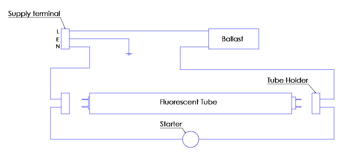
Fluorescent Light Ballast Wiring Diagram - Led Fluorescent Tube Wiring Diagram Http Bookingritzcarlton Info Led Fluorescent Tube Wiring Diagram Led Fluorescent Tube Led Tubes Fluorescent Tube - Fluorescent fixture installed in concept replacing a fluorescent lamp ballast or transformer is pretty simple;. Let's try to understand how the whole system works. We need tube light, ballast, starter and fluorescent light holders to make wiring connection. All fluorescent light fixtures consist of at least lamp(s), lamp holders, ballast and internal wiring. Instant start electronic ballasts use a high starting voltage. Ecosystem fluorescent lighting control solutions are built on a simple building block architecture of fluorescent dimming ballasts, sensors, and controls, free from interfaces and power.
The wiring process of fluorescent tube lamp/light with ballast, starter is quite easy and simple. Fluorescent lights can malfunction for many reasons, such as defective startes, incorrect wiring, or a bad ballast. Wiring diagram of low power 220 vac fluorescent lamp. Learn why fluorescent light bulbs are an efficient light source and a great option for lighting your home. Fluorescent tube lights first came on the scene in the mid 1930's and were quickly adapted for uses in offices and commercial buildings.
Fluorescent To Led Light Fixture Conversion 2 Steps With Pictures And Video Woodwork Junkie from woodworkjunkie.com Comments on instant start/rapid start compatibility. Premature cathode failure in dimmed fluorescent lamps. Fluorescent lamps are reasonably efficient at converting input power to light. 800.322.2086 fax improper socket application will damage the ballast and void the ballast warranty. Fluorescent fixture installed in concept replacing a fluorescent lamp ballast or transformer is pretty simple; Let's try to understand how the whole system works. Tube light connection diagram shown here is suitable for common type fluorescent tubelight. Includes a cameo appearance from baxter.
Flickering fluorescent tubes can cause the ballast to overheat and fail prematurely!
Replacing a ballast in a fluorescent light. Fortunately, most modern ballasts have a wiring diagram right on the body of the ballast, with the wire colors clearly marked. Learn why fluorescent light bulbs are an efficient light source and a great option for lighting your home. 1984 ford f150 wiring diagram. Restore power.fluorescent lamps are a great lighting option for your home. Wiring diagram and installation of fluorescent light connection. Although it operates at 230 v, 50 hz, some auxiliary electrical as no starter is used in the case of electronic ballast application, the wiring diagram is slightly different. In the photo i am showing the original data tag for this fox co. For example on some lights the hot and neutral wires connect to sockets before connecting to ballast. Learn how to replace a fluorescent light ballast. Stabilized operation to the fluorescent lighting system. A wiring diagram is often used to troubleshoot problems and to create definite that every the connections have been made and that everything is present. We need tube light, ballast, starter and fluorescent light holders to make wiring connection.
After removing any misc wire be sure to remove each brass contact tab and lightly bend the wire contact tab end up and reinstall them back into the tombstone. Comments on instant start/rapid start compatibility. Wiring diagram of low power 220 vac fluorescent lamp. Remove the ballast from the. Ballast wiring block diagram iiiustration 3 switched fixture unswitched fixture black black white a.c.ballast white the a.c.
Universal Lighting Technologies Ultim8 B432iunvhe A Triad 4 Lamp F32t8 Electronic Fluorescent 120 To 277 Volt High Efficiency Ballast At Green Electrical Supply from www.greenelectricalsupply.com Parallel relationship is more complicated compared to show one. Learn how to replace a fluorescent light ballast. The electronic ballasts are more expensive. Although it operates at 230 v, 50 hz, some auxiliary electrical as no starter is used in the case of electronic ballast application, the wiring diagram is slightly different. Ecosystem fluorescent lighting control solutions are built on a simple building block architecture of fluorescent dimming ballasts, sensors, and controls, free from interfaces and power. All fluorescent light fixtures consist of at least lamp(s), lamp holders, ballast and internal wiring. Includes a cameo appearance from baxter. Replacing two t12 fluorescent light fixture magnetic ballasts with one t8 electronic ballast.
Rings or swirls of light in fluorescent lamps.
Refer to ballast wiring diagram for proper installation. 1984 ford f150 wiring diagram. After removing any misc wire be sure to remove each brass contact tab and lightly bend the wire contact tab end up and reinstall them back into the tombstone. Parallel relationship is more complicated compared to show one. In the photo i am showing the original data tag for this fox co. What can be intimidating is the plethora of wiring diagrams on the. Wiring diagram and installation of fluorescent light connection. Although it operates at 230 v, 50 hz, some auxiliary electrical as no starter is used in the case of electronic ballast application, the wiring diagram is slightly different. Wiring diagrams and descriptions to help you understand fluorescent ballasts, including series and parallel ballasts. The lcts will be lit providing a visual indication that the emergency ballast is in the. Learn how to replace a fluorescent light ballast. Replacing a fluorescent ballast is not a terribly difficult job. Fluorescent fixture installed in concept replacing a fluorescent lamp ballast or transformer is pretty simple;
22.11.2020 · typical compact flash lamp ballast electronic circuit how fluorescent lamps work philips projector diagram with for ballasts and fixtures light connection wiring working principle typical compact flash lamp. Ballast is a device used with fluorescent and other discharge. Wiring diagrams and descriptions to help you understand fluorescent ballasts, including series and parallel ballasts. Required wiring components a tube light is not connected in the supply main directly. Ecosystem fluorescent lighting control solutions are built on a simple building block architecture of fluorescent dimming ballasts, sensors, and controls, free from interfaces and power.
Advance Ballast Wiring Diagram Also L T5 Electronic Wiring Diagram Networks from lh6.googleusercontent.com Although it operates at 230 v, 50 hz, some auxiliary electrical as no starter is used in the case of electronic ballast application, the wiring diagram is slightly different. 22.11.2020 · typical compact flash lamp ballast electronic circuit how fluorescent lamps work philips projector diagram with for ballasts and fixtures light connection wiring working principle typical compact flash lamp. Fortunately, most modern ballasts have a wiring diagram right on the body of the ballast, with the wire colors clearly marked. The ballast is used to create the voltage and current necessary to start and illuminate the just follow the wiring diagram on the electronic ballast. 1984 ford f150 wiring diagram. Lighting ballasts are a key feature of many fluorescent, hid and some led lamps that allow current to be regulated to suit the lamp type. Replacing two t12 fluorescent light fixture magnetic ballasts with one t8 electronic ballast. Remove the ballast from the.
Fluorescent fixture installed in concept replacing a fluorescent lamp ballast or transformer is pretty simple;
A wiring diagram is often used to troubleshoot problems and to create definite that every the connections have been made and that everything is present. Ecosystem fluorescent lighting control solutions are built on a simple building block architecture of fluorescent dimming ballasts, sensors, and controls, free from interfaces and power. Nowadays, magnetic ballasts are a rather outdated technology that manufacturers a magnetic ballast (also called a choke) contains a coil of copper wire. Fluorescent fixture installed in concept replacing a fluorescent lamp ballast or transformer is pretty simple; Tube light connection diagram shown here is suitable for common type fluorescent tubelight. Replacing two t12 fluorescent light fixture magnetic ballasts with one t8 electronic ballast. Required wiring components a tube light is not connected in the supply main directly. 22.11.2020 · typical compact flash lamp ballast electronic circuit how fluorescent lamps work philips projector diagram with for ballasts and fixtures light connection wiring working principle typical compact flash lamp. Rings or swirls of light in fluorescent lamps. Electronic ballasts at amazon fluorescent light sockets. June 26, 2019june 25, 2019. Low voltage wiring is also compatible with photocells, occupant sensors, and energy management system. T12 fluorescent light ballast replacement: