Home
› Wiring Diagram Vs Schematic / Electrical Diagrams And Schematics Instrumentation Tools - Use wiring diagrams to assist in building or manufacturing the circuit or electronic device.
Wiring Diagram Vs Schematic / Electrical Diagrams And Schematics Instrumentation Tools - Use wiring diagrams to assist in building or manufacturing the circuit or electronic device.
Wiring Diagram Vs Schematic / Electrical Diagrams And Schematics Instrumentation Tools - Use wiring diagrams to assist in building or manufacturing the circuit or electronic device.. Car wiring diagram software provide the whole view of the wiring diagram in a car,component location diagram and maintenance method. Wiring diagram a wiring diagram shows, as closely as possible, the actual location of all component 12 14 22 24 a2 vs dashed lines represent optional contacts (diaw and duaw devices only). Customize hundreds of electrical symbols and quickly drop them into your wiring diagram. Graphic interchange format 39.1 kb. Class 8502 type pe contactor w/ class 9065 type te overload relay.
Wiring diagram a wiring diagram shows, as closely as possible, the actual location of all component 12 14 22 24 a2 vs dashed lines represent optional contacts (diaw and duaw devices only). Installation schematics and wiring diagrams: Lamp wire for panel 6. Launch it instantly with one click. It shows the components of the circuit as simplified shapes, and the faculty and signal friends amongst the devices.
Schematics Com Free Online Schematic Drawing Tool from schematics-prod.s3.amazonaws.com Hi, i'm trying to emulate a previous engineer's wiring diagram drawings, and was wondering if anyone has insight on the best way to do it. Graphic interchange format 39.1 kb. Symbols you should know wiring a wiring diagram is a visual representation of components and wires related to an electrical connection. Wiring diagrams are made up of two things: I wonder if scheme or schematic are different in the following example, or if they are synonyms. Please see attached screen capture from.pdf file. The electric scheme never shows the actual image of a set of objects, but only shows their connection with each other. (4) specifier + head + complement now, we have already argued in the case of noun.
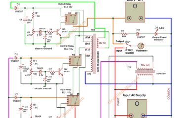
Wiring diagrams are generally used for larger devices, which employ actual wire and focus more on the connections of electrical components.
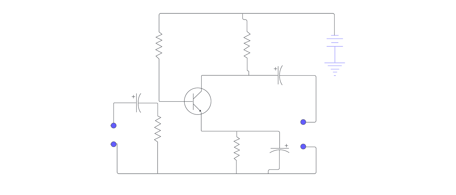
A wiring diagram shows how wires and components are connected, but not necessarily in logical order. Most troubleshooters prefer schematic diagrams. (4) specifier + head + complement now, we have already argued in the case of noun. Wiring diagram a wiring diagram shows, as closely as possible, the actual location of all component 12 14 22 24 a2 vs dashed lines represent optional contacts (diaw and duaw devices only). C15 cat engine wiring schematics [gif, e. Wiring diagrams are generally used for larger devices, which employ actual wire and focus more on the connections of electrical components. * given the terminology we have introduced here, we can say that all of the bracketed phrases in (3) above are of the schematic form (4) below: A wiring diagram is a simplified conventional pictorial representation of an electrical circuit. Wiring diagrams are made up of two things: The electric scheme never shows the actual image of a set of objects, but only shows their connection with each other. Caterpillar 246c shematics electrical wiring diagram pdf, eng, 927 kb. Do you these wiring diagrams are literally just sketches? Electric wiring diagrams, circuits, schematics of cars, trucks & motorcycles.
It shows the components of the circuit as simplified shapes, and the power and signal connections between the devices. Start date oct 1, 2008. Car wiring diagram software provide the whole view of the wiring diagram in a car,component location diagram and maintenance method. Common sense schematics let you name a node +5v and know that the simulator will do the right thing automatically, keeping your schematics compact and elegant. A wiring diagram is a type of schematic that uses abstract pictorial symbols to show all the interconnections of components in a system.
Difference Between Pictorial And Schematic Diagrams Lucidchart Blog from cdn-cashy-static-assets.lucidchart.com Wiring diagram lvds for panel vga input. Hi, i'm trying to emulate a previous engineer's wiring diagram drawings, and was wondering if anyone has insight on the best way to do it. A schematic diagram is a circuit which shows the connections in a clear and standardized way. Graphic interchange format 39.1 kb. It shows the components of the circuit as simplified shapes, and the faculty and signal friends amongst the devices. A wiring diagram is a type of schematic that uses abstract pictorial symbols to show all the interconnections of components in a system. Do you these wiring diagrams are literally just sketches? Use wiring diagrams to assist in building or manufacturing the circuit or electronic device.
I wonder if scheme or schematic are different in the following example, or if they are synonyms.
Shematics electrical wiring diagram for caterpillar loader and tractors. A wiring diagram is a simplified conventional pictorial representation of an electrical circuit. A schematic, or schematic diagram, represents the elements of a system with abstract and graphic symbols instead of realistic pictures. A wiring diagram or schematic is a visual representation of the connections the following reference sections provide installation documents and wiring diagram schematics for maglocks door access system components, kits and equipment. Wiring diagram a wiring diagram shows, as closely as possible, the actual location of all component 12 14 22 24 a2 vs dashed lines represent optional contacts (diaw and duaw devices only). An electronic schematic is a diagram that uses standardized electronic and electrical symbols to show how individual components are connected. Installation schematics and wiring diagrams: If so, which is most commonly used? Do you these wiring diagrams are literally just sketches? The electric scheme never shows the actual image of a set of objects, but only shows their connection with each other. They are also useful for making repairs. A wiring diagram usually gives suggestion roughly the relative slant. Fellow author throbscottle has created a great instructable on how to reverse engineer a schematic from a circuit board.
Symbols you should know wiring a wiring diagram is a visual representation of components and wires related to an electrical connection. Wiring diagram lvds for panel vga input. They are also useful for making repairs. Wouldn't it be nice if you could get the full schematics, interior photos, and other technical detail before you even pick up a screwdriver? Wiring diagrams are generally used for larger devices, which employ actual wire and focus more on the connections of electrical components.
Electronics Circuit Diagram Schematic Diagram Projects Tutorials from circuitspedia.com The electric scheme never shows the actual image of a set of objects, but only shows their connection with each other. This pictorial diagram shows us the physical links that are. Type 2 wiring diagrams contributions to this section are always welcome. It shows the components of the circuit as simplified shapes, and the faculty and signal friends amongst the devices. What you do is to enter the chassis number, and then you will get. Most troubleshooters prefer schematic diagrams. Use wiring diagrams to assist in building or manufacturing the circuit or electronic device. Symbols you should know wiring a wiring diagram is a visual representation of components and wires related to an electrical connection.
* given the terminology we have introduced here, we can say that all of the bracketed phrases in (3) above are of the schematic form (4) below:
Wiring diagrams are made up of two things: A wiring diagram shows how wires and components are connected, but not necessarily in logical order. Learn vocabulary, terms and more with flashcards, games schematic diagrams break the wiring of control systems down into a(n) the schematic ladder diagram resembles a ladder in that it is made up of two vertical lines representing. Start studying chapter 6 reading schematic diagrams. Please see attached screen capture from.pdf file. Usually, the electrical wiring diagram of any hvac equipment can be acquired from the manufacturer of this equipment who provides the electrical wiring diagram in the user's manual (see fig.1) or sometimes on the equipment itself (see fig.2). Fellow author throbscottle has created a great instructable on how to reverse engineer a schematic from a circuit board. A proper wiring diagram will be labeled and show connections in a way that prevents confusion about how connections are made. A schematic, or schematic diagram, represents the elements of a system with abstract and graphic symbols instead of realistic pictures. This pictorial diagram shows us the physical links that are. What you do is to enter the chassis number, and then you will get. Type 2 wiring diagrams contributions to this section are always welcome. A schematic diagram focuses more on comprehending and spreading information rather than doing physical operations.