Home
› Full Wave Rectifier Circuit Diagram In Multisim : Solved 1 Half Wave Rectifier In Half Wave Rectification Chegg Com - How to use multisim oscilloscope on a rc series circuit.
Full Wave Rectifier Circuit Diagram In Multisim : Solved 1 Half Wave Rectifier In Half Wave Rectification Chegg Com - How to use multisim oscilloscope on a rc series circuit.
Full Wave Rectifier Circuit Diagram In Multisim : Solved 1 Half Wave Rectifier In Half Wave Rectification Chegg Com - How to use multisim oscilloscope on a rc series circuit.. In order to reduce the ripple in waveform or to make the waveform continuous we have to add a capacitor filter in the output. Along with some filters to remove ripples we can. It is generally used as educational tool for the rectifier used in the simulation is full wave rectifier circuit. However, any circuit that uses an opamp, transformer, controlled source or. You can see that 4 diodes are connected in a bridge kind of structure and the oscilloscope is connected across the full wave rectifier output waveforms.
It will pass the positive pat as it is and will invert the negative part of the wave to appear like positive on the load with the help of a bridge as you will see shortly. The full wave rectifier circuit consists of two power diodes connected to a single load resistance (rl) with each diode taking it in turn to supply current to the load. · double click ac_power set its value above mentioned. Multisim is a schematic capture and simulation program for analog, digital and mixed analog/digital circuits, and is one application program of the national instruments circuit design suite, which also includes printed circuit board design tools and an interface to the elvis breadboarding platform. Pn junction diode vi characteristics using multisim.
Full Wave Rectifier Circuit Diagram Multisim Page 1 Line 17qq Com from img.17qq.com Full wave rectifier circuit diagram. Use the chrome™ browser to best experience multisim live. This circuit is a simple resistive voltage divider excited by a voltage sine wave (available as an. However, any circuit that uses an opamp, transformer, controlled source or oscilloscope must be tip the battery in multisim has no resistance. Full wave rectifier with multisim bridge and centertap circuits. Simulating halfwave and fullwave rectifier circuit in multisim or how to prepare halfwave and fullwave rectifier circuit in multisim is. Simulation of full wave precision rectifier using multisim, circuit diagram working principle, expected waveforms, components. If you want to use a battery in parallel with.
如何制造全波桥式整流器。 simulating half wave rectifier circuit on multisim.
However, any circuit that uses an opamp, transformer, controlled source or. How to use multisim oscilloscope on a rc series circuit. Full wave rectifier is the semiconductor device which converts complete cycle of ac into pulsating dc. Start by insuring the current full wave bridge 1 circuit looks like that shown below: 如何制造全波桥式整流器。 simulating half wave rectifier circuit on multisim. Thus, this type of rectifier. The smoothness of dc value is not much. A single phase full wave diode bridge rectifier circuit using multisim 12.0. Full wave rectifier with center tapped transformer. It will pass the positive pat as it is and will invert the negative part of the wave to appear like positive on the load with the help of a bridge as you will see shortly. Simulating halfwave and fullwave rectifier circuit in multisim or how to prepare halfwave and fullwave rectifier circuit in multisim is. It is generally used as educational tool for the rectifier used in the simulation is full wave rectifier circuit. If you want to use a battery in parallel with.
Single wave rectification can be achieved by using either a half wave or full wave rectification this filter applies a smoothing effect allowing the dc output to be maintained. Electronics tutorial about the full wave rectifier also known as a bridge rectifier and full wave bridge rectifier theory. · draw the schematic diagram of the above circuit with fixed voltage regulator. In full wave bridge rectifier, an ordinary transformer is used in place of a center tapped transformer. How to make full wave bridge rectifier.
Grundlagen Http Sites Prenninger Com Ewb V5 12 Multisim Grundlagen Http Www Linksammlung Info Http Www Schaltungen At Wels Am 2015 04 01 Bitte Nutzen Sie Doch Rechts Oben Das Suchfeld Diese Site Durchsuchen Din A3 Oder Din A4 Quer from www.ni.com Microcontroller simulation is included in multisim. I was playing in multisim 11 and can't seem to get a full wave rectifier to work. Start by insuring the current full wave bridge 1 circuit looks like that shown below: In full wave bridge rectifier, an ordinary transformer is used in place of a center tapped transformer. Multisim is set up so that multiple instrument components can each be monitoring the same. The circuit diagram of the full wave bridge rectifier is shown below. In order to reduce the ripple in waveform or to make the waveform continuous we have to add a capacitor filter in the output. And i put the values randomly so , if you get any pic you can use it.
Thus, this type of rectifier.
Start by insuring the current full wave bridge 1 circuit looks like that shown below: A single phase full wave diode bridge rectifier circuit using multisim 12.0. The circuit is not suitable when a small voltage is required to be rectified. Full wave rectifier is the semiconductor device which converts complete cycle of ac into pulsating dc. I forgot to mention that i didn't see any diagram. Multisim is a schematic capture and simulation program for analog, digital and mixed analog/digital circuits, and is one application program of the national instruments circuit design suite, which also includes printed circuit board design tools and an interface to the elvis breadboarding platform. However, any circuit that uses an opamp, transformer, controlled source or oscilloscope must be tip the battery in multisim has no resistance. Looking at the circuit diagram above, we see a clever circuit design comprising both, the oscillator as well as the pwm optimization feature included. The smoothness of dc value is not much. Full wave rectifier with center tapped transformer. How to use multisim oscilloscope on a rc series circuit. A full wave rectifier however uses both the positive and negative parts of the ac wave to rectify. Full wave rectifier circuit diagram.
Here, the gates n1 and n2 are wired up as an oscillator, which primarily generates perfectly uniform square wave pulses at its output. Single wave rectification can be achieved by using either a half wave or full wave rectification this filter applies a smoothing effect allowing the dc output to be maintained. 如何制造全波桥式整流器。 simulating half wave rectifier circuit on multisim. Simulation of full wave precision rectifier using multisim, circuit diagram working principle, expected waveforms, components. Full wave rectifier circuit diagram.
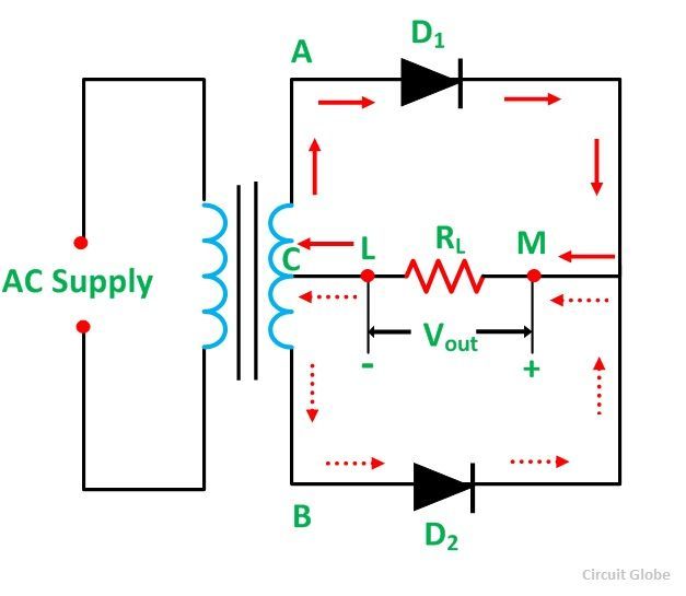
Center Tapped Full Wave Rectifier Its Operation And Wave Diagram Circuit Globe from circuitglobe.com Single wave rectification can be achieved by using either a half wave or full wave rectification this filter applies a smoothing effect allowing the dc output to be maintained. In order to reduce the ripple in waveform or to make the waveform continuous we have to add a capacitor filter in the output. And i put the values randomly so , if you get any pic you can use it. Full wave rectifier with multisim bridge and centertap circuits. Looking at the circuit diagram above, we see a clever circuit design comprising both, the oscillator as well as the pwm optimization feature included. The circuit diagram of the full wave bridge rectifier is shown below. Email thisblogthis!share to twittershare to facebook. Use the chrome™ browser to best experience multisim live.
I was playing in multisim 11 and can't seem to get a full wave rectifier to work.
Microcontroller simulation is included in multisim. Full wave rectifier is the semiconductor device which converts complete cycle of ac into pulsating dc. A single phase full wave diode bridge rectifier circuit using multisim 12.0. Full wave bridge rectifier circuit multisim simulation. If you want to use a battery in parallel with. Working details of bridge rectifier. A full wave rectifier however uses both the positive and negative parts of the ac wave to rectify. Here, the gates n1 and n2 are wired up as an oscillator, which primarily generates perfectly uniform square wave pulses at its output. The full wave rectifier circuit consists of two power diodes connected to a single load resistance (rl) with each diode taking it in turn to supply current to the load. However, any circuit that uses an opamp, transformer, controlled source or. Start by insuring the current full wave bridge 1 circuit looks like that shown below: You can see that 4 diodes are connected in a bridge kind of structure and the oscilloscope is connected across the full wave rectifier output waveforms. Multisim is set up so that multiple instrument components can each be monitoring the same.