Home
› Sg3525 Inverter Circuit Diagram Pdf - Sg3525 Inverter Circuit With Output Voltage Correction : Activating this circuit by applying a positive signal on pin 10 performs two functions:
Sg3525 Inverter Circuit Diagram Pdf - Sg3525 Inverter Circuit With Output Voltage Correction : Activating this circuit by applying a positive signal on pin 10 performs two functions:
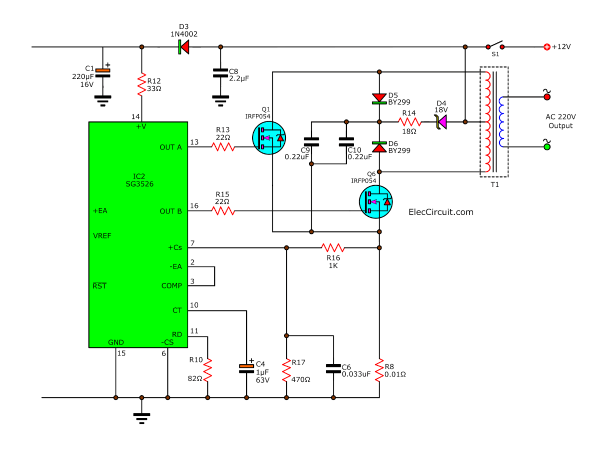
Sg3525 Inverter Circuit Diagram Pdf - Sg3525 Inverter Circuit With Output Voltage Correction : Activating this circuit by applying a positive signal on pin 10 performs two functions:. Voltage 220vac acquired by means of alternately switching windings of the transformer ts1. Schematic diagram of the inverter exhibits the fig.1. Electrical characteristics (v# i = 20 v, and over operating temperature, unless otherwise specified). Grated circuits are designed to offer improved per The proposed sg3535 inverter circuit with output correction has been tested practically and worked well with outstanding accuracy.
This design is actually an universal design which may be implemented for upgrading all complete circuit diagram and pcb layout for the proposed sg3525 pure sine wave inverter circuit. Schematic diagram of the inverter exhibits the fig.1. Onsemi, alldatasheet, datasheet, datasheet search site for electronic components and semiconductors, integrated circuits, diodes, triacs, and other semiconductors. A synchronization input to the oscillator allows multiple units to be supplied or a single unit to be synchronized to an external. Sg3525 sg2525 2 sg3525 sync sg3525 high voltage sg3525 internal diagram amplifier sg3525 sg1525.
How To Build 200w Inverter Circuit Diagram Project Eleccircuit Com from www.eleccircuit.com Grated circuits are designed to offer improved per The minimum gm specification is used to calculate minimum gv when the error amplifier output is loaded. Keep reading if you want to know about inverter circuit using sg3525 ic. Schematic diagram of the inverter exhibits the fig.1. A typical circuit design for converting the sg3525 waveform into a pure sinewave waveform is shown below. Pwm is used in all sorts of power control and converter circuits. How to make inverter using sg3525 ic. Activating this circuit by applying a positive signal on pin 10 performs two functions:
Onsemi, alldatasheet, datasheet, datasheet search site for electronic components and semiconductors, integrated circuits, diodes, triacs, and other semiconductors.
Sg3525 datasheet, cross reference, circuit and application notes in pdf format. Latch is immediately set providing the fastest turn−off signal to the outputs; Electrical characteristics (v# i = 20 v, and over operating temperature, unless otherwise specified). Schematic diagram of the inverter exhibits the fig.1. The first circuit is equipped with a low battery detection and … ® sg2525a sg3525a regulating pulse width modulators. The post explains a 3 powerful yet simple sine wave 12v inverter circuits using a single ic sg 3525. Hi, in today's video i'll show you how to make a regulated power inverter with the popular sg3525 or uc3525 pwm ic. Circuit diagram of sg3525 inverter 50 watt inverter circuit diagram circuit diagram images: Pwm is used in all sorts of power control and converter circuits. Grated circuits are designed to offer improved per For pcb layout visit my website in this video you will see detailed circuit diagram and split type circuit to understand each part function and easy way for making. Sg3525 sg2525 2 sg3525 sync sg3525 high voltage sg3525 internal diagram amplifier sg3525 sg1525.
Grated circuits are designed to offer improved per Schematic diagram of the inverter exhibits the fig.1. You are here this article is all about sg3525 inverter circuit and sg3525 pinout and its ic number. There are numerous pwm controllers available that make the use and application of pwm quite easy. It has a protection circuitry that shutdown the pwm signal based on the feedback current limit.
Circuit Diagram Of Sg3525 Inverter Welding Machine Page 1 Line 17qq Com from pic.17qq.com Activating this circuit by applying a positive signal on pin 10 performs two functions: Step by step sg3525 inverter circuit diagram and sg3525 pinout. It has a protection circuitry that shutdown the pwm signal based on the feedback current limit. Application information shutdown options (see block diagram, front page) latch is immediately set providing the fastest turnoff signal to since both the compensation and softstart terminals the. A synchronization input to the oscillator allows multiple units to be supplied or a single unit to be synchronized to an external. ® sg2525a sg3525a regulating pulse width modulators. Sg3525 circuits sg3525 projects sg3525 pulse width modulator pwm control integrated, can be used for the control of all kinds of switched power supply. Pwm is used in all sorts of power control and converter circuits.
Pulse width modulator control circuits. ® sg2525a sg3525a regulating pulse width modulators. How to make inverter using sg3525 ic. For pcb layout visit my website in this video you will see detailed circuit diagram and split type circuit to understand each part function and easy way for making. Sg3525 application circuit diagram sg3525 drive by wire circuit sg3525 inverter circuit sg3525an sg3525 smps switching power supply design, circuit diagrams, a guide to smps switching advanced smps transformer design program excellentit and ir2153 sg3525. A typical circuit design for converting the sg3525 waveform into a pure sinewave waveform is shown below. The minimum gm specification is used to calculate minimum gv when the error amplifier output is loaded. There are numerous pwm controllers available that make the use and application of pwm quite easy. Pwm is used in all sorts of power control and converter circuits. 3 high power sg3525 pure sinewave inverter circuits | homemade circuit projects. Application information shutdown options (see block diagram, front page) latch is immediately set providing the fastest turnoff signal to since both the compensation and softstart terminals the. Pwm is used in all sorts of power control and converter circuits. Onsemi, alldatasheet, datasheet, datasheet search site for electronic components and semiconductors, integrated circuits, diodes, triacs, and other semiconductors.
The sg3525a pulse width modulator control circuit offers improved performance and lower external parts count when implemented for controlling all types of switching power supplies. You are here this article is all about sg3525 inverter circuit and sg3525 pinout and its ic number. Latch is immediately set providing the fastest turn−off signal to the outputs; Application information shutdown options (see block diagram, front page) latch is immediately set providing the fastest turnoff signal to since both the compensation and softstart terminals the. Sg3525 datasheet, cross reference, circuit and application notes in pdf format.
Sg3525 Power Inverter Circuit With Voltage Regulation Complete Video Tutorial Youtube from i.ytimg.com Pwm is used in all sorts of power control and converter circuits. This design is actually an universal design which may be implemented for upgrading all complete circuit diagram and pcb layout for the proposed sg3525 pure sine wave inverter circuit. Latch is immediately set providing the fastest turn−off signal to the outputs; A synchronization input to the oscillator allows multiple units to be supplied or a single unit to be synchronized to an external. Hi, in today's video i'll show you how to make a regulated power inverter with the popular sg3525 or uc3525 pwm ic. Voltage 220vac acquired by means of alternately switching windings of the transformer ts1. The on−chip +5.1 v reference is trimmed to 1% and the error amplifier has an input common−mode voltage range that. Its a sg3525 pwm circuit with 50hz and it converts dc to ac ( inverter circuit diagram 12v to 220v ).
Diagram] ka3525 inverter circuit diagram full version hd quality circuit diagram.
Latch is immediately set providing the fastest turn−off signal to the outputs; Another feature of these pwm circuits is a latch following the. Pulse width modulator control circuits. Sg3525 datasheet, cross reference, circuit and application notes in pdf format. Voltage 220vac acquired by means of alternately switching windings of the transformer ts1. Sg3525 sg2525 2 sg3525 sync sg3525 high voltage sg3525 internal diagram amplifier sg3525 sg1525. Diagram] ka3525 inverter circuit diagram full version hd quality circuit diagram. Hi, in today's video i'll show you how to make a regulated power inverter with the popular sg3525 or uc3525 pwm ic. A typical circuit design for converting the sg3525 waveform into a pure sinewave waveform is shown below. Ka3525 inverter circuit diagram pdf fileread ka3525 sg3525a pulse width modulator control circuit. Schematic diagram of the inverter exhibits the fig.1. Sg3525 circuits sg3525 projects sg3525 pulse width modulator pwm control integrated, can be used for the control of all kinds of switched power supply. There are numerous pwm controllers available that make the use and application of pwm quite easy.