Home
› Dc Motor Schematic Diagram : Brushless DC motor schematic diagram. | Download Scientific Diagram : The circuit diagram, block diagram and transfer function of these are given below:
Dc Motor Schematic Diagram : Brushless DC motor schematic diagram. | Download Scientific Diagram : The circuit diagram, block diagram and transfer function of these are given below:
Dc Motor Schematic Diagram : Brushless DC motor schematic diagram. | Download Scientific Diagram : The circuit diagram, block diagram and transfer function of these are given below:. Procedure following is the schematic diagram of the dc motor interface to arduino uno board. Use figure 1 if your motor has a single voltage shunt field. Dc shunt motor circuit diagram in case of the shunt wound dc motor, this current supply will divide into two ways like ia,& ish, where 'ia' will supply throughout the 'ra' resistance armature winding. The armature is perpendicular to the axis of the cylinder. A dc motor is any of a class of rotary electrical motors that converts direct current electrical energy into mechanical energy.
A dc motor is composed of the following main parts:: With the transistors that are used by the library, when flat side of the transistor facing you the left leg is the emitter, the middle leg is the base Dc shunt motor circuit diagram in case of the shunt wound dc motor, this current supply will divide into two ways like ia,& ish, where 'ia' will supply throughout the 'ra' resistance armature winding. The circuit diagram, block diagram and transfer function of these are given below: The cd motor is always driven by a power amplifier that acts as an energy source.
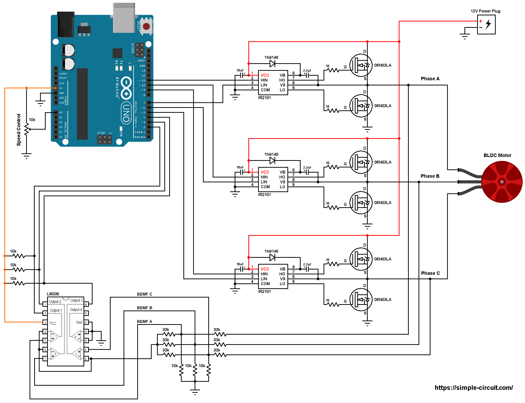
BLDC Motor control using Arduino | Speed control with potentiometer from simple-circuit.com Complete circuit diagram for the motor controller along with the parts list has been included here. It demonstrates how the electric cords are interconnected. A simple pwm motor speed control circuit with diagram and schematic for low power dc motors. The timer chip which applied in this circuit will be an nmos dual timer/oscillator ne556. 10+ 12v 5a dc motor speed control circuit diagram. If you want to know what is dc series motor, how it works and how its circuit diagram is made, then this post may be important for you. A dc motor converts electrical energy into mechanical energy. There are three input pins for each motor, input1 (in1), input2 (in2), and enable1 (en1) for motor1 and input3, input4, and enable2 for motor2.
Let's understand the meaning of the letters marked in this diagram.
On the other hand, when the wiper arm of vr1 is at the bottom position, c1. A simple pwm motor speed control circuit with diagram and schematic for low power dc motors. • implement a transistor circuit and arduino program for pwm control of the dc motor! Dc motor driver circuit diagram fresh brushed dc motors research two speed motor wiring diagram 3 phase unique patent us noise exactly what is a wiring diagram? With the transistors that are used by the library, when flat side of the transistor facing you the left leg is the emitter, the middle leg is the base A direct current is named according to the connection of the field winding with the armature. A dc motor is composed of the following main parts:: Dc motor working principle, construction and diagram explanation it's very important to know about the dc motor working principle and construction in order to master the basics of dc machines. In the same way, 'ish' will supply through the 'rsh' resistance field winding. Motor connections your motor will be internally connected according to one of the diagrams shown below. The field coils or field windings are energised by a separate dc source as shown in the circuit diagram shown below: E1 & e2 shunt field winding terminals; 10+ 12v 5a dc motor speed control circuit diagram.
It demonstrates how the electric cords are interconnected. A wiring diagram is an easy visual depiction of the physical links and also physical design of an electric system or circuit. The field coils or field windings are energised by a separate dc source as shown in the circuit diagram shown below: Procedure following is the schematic diagram of the dc motor interface to arduino uno board. Nearly all types of dc motors have some internal mechanism, either electromechanical or electronic, to periodically change the direction of current in part of the motor.
brushless dc motor - What PWM inputs are needed to drive a 3 phase BLDC using the HIP4086 IC ... from i.stack.imgur.com 10+ 12v 5a dc motor speed control circuit diagram. Let's understand the meaning of the letters marked in this diagram. The above diagram shows how to connect the l298 ic to control two motors. Motor connections your motor will be internally connected according to one of the diagrams shown below. Dc shunt motor circuit diagram in case of the shunt wound dc motor, this current supply will divide into two ways like ia,& ish, where 'ia' will supply throughout the 'ra' resistance armature winding. Simplified bldc motor diagrams author: There are three input pins for each motor, input1 (in1), input2 (in2), and enable1 (en1) for motor1 and input3, input4, and enable2 for motor2. Dc motor reversing switch the circuit diagram for easiest way to reverse electric how do i run a or actuator help wiring relay forward control circuits ladder logic direction using wire mgr electrical controller build starters page reversal sw182 type contactor single phase split motors and applied 12 volt solenoid schematic rotation of 2 micro.
Ward brown microchip technology inc.
The above diagram shows how to connect the l298 ic to control two motors. As you may witness, although the bulb works perfectly in response to the pwms and varies its intensity from minimum glow to. In the above video clip we can see how the ic 555 based design is used for controlling speed of a dc motor. A simple pwm motor speed control circuit with diagram and schematic for low power dc motors. A wiring diagram is an easy visual depiction of the physical links and also physical design of an electric system or circuit. Dc shunt motor circuit diagram in case of the shunt wound dc motor, this current supply will divide into two ways like ia,& ish, where 'ia' will supply throughout the 'ra' resistance armature winding. An automatic starter operates in a similar fashion, except that automatic relays short out sections of the starter resistance either by a time sequence or when the armature current drops to a selected value. Dc motor/amplifier system block diagram. This easy to make pwm dc motor controller is made using ic cd40106b This is the schematic diagram of dc motor speed controller circuit. Motor connections your motor will be internally connected according to one of the diagrams shown below. Use figure 2 if your motor has a dual voltage shunt field. Vm is the power supply for motor and its value depends on the motors voltage rating.
Use figure 1 if your motor has a single voltage shunt field. The armature of a dc motor is a cylinder of magnetic laminations that are insulated from one another. A dc motor is any of a class of rotary electrical motors that converts direct current electrical energy into mechanical energy. On the other hand, when the wiper arm of vr1 is at the bottom position, c1. This is the schematic diagram of dc motor speed controller circuit.
Types of Single Phase Induction Motors | Single Phase Induction Motor Wiring Diagram ... from electricala2z.com Hi, readers welcome to the new post. Ward brown microchip technology inc. Vm is the power supply for motor and its value depends on the motors voltage rating. Dc motor working principle, construction and diagram explanation it's very important to know about the dc motor working principle and construction in order to master the basics of dc machines. • describe how pwm controls dc motor speed! Use figure 2 if your motor has a dual voltage shunt field. With the transistors that are used by the library, when flat side of the transistor facing you the left leg is the emitter, the middle leg is the base Armature controlled dc servomotor circuit diagram in this motor, the field current is held constant and armature current is varied to control the torque.
N s a c a a b b c c b com com com n n s s 110 010 011 101 100 001 n s s n 6 3 4 1 2 5 a c b c b a com brushless dc motor control made easy
Complete circuit diagram for the motor controller along with the parts list has been included here. Vm is the power supply for motor and its value depends on the motors voltage rating. Circuit diagram of dc series motor When the wiper arm of potmeter vr1 is in top position, capacitor c1 charges through r1, r2 and d1 and produces a pulse train at the output of ic1 with long negative and short positive pulse widths. If you want to know what is dc series motor, how it works and how its circuit diagram is made, then this post may be important for you. • explain the role of a snubber diode! Dc motor diagram different parts of a dc motor. The most common types rely on the forces produced by magnetic fields. A dc motor is any of a class of rotary electrical motors that converts direct current electrical energy into mechanical energy. In this section, we will be discussing the construction of dc motors. Dc motors diagrams & code brown county library warning: The speed is controlled through an externally applied varying dc voltage source. The circuit diagram, block diagram and transfer function of these are given below: