Home
› Electric Circuit Diagram Symbols - Electric Circuit Diagrams: Lesson for Kids - Video & Lesson Transcript | Study.com - A ground symbol (iec symbol 5017) identifies a ground terminal.
Electric Circuit Diagram Symbols - Electric Circuit Diagrams: Lesson for Kids - Video & Lesson Transcript | Study.com - A ground symbol (iec symbol 5017) identifies a ground terminal.
Electric Circuit Diagram Symbols - Electric Circuit Diagrams: Lesson for Kids - Video & Lesson Transcript | Study.com - A ground symbol (iec symbol 5017) identifies a ground terminal.. All electric circuits must have a voltage source, such as a battery, and a conductor, which is usually wire. An electric circuit is a path in which electrons from a voltage or current source flow. A circuit diagram (electrical diagram, elementary diagram, electronic schematic) is a graphical representation of an electrical circuit. In complex diagrams it is often necessary to draw wires crossing even though they are not connected. What is an electric circuit.
These diagrams are drawn using standard industrial symbols. From transistors to logic gates whether you're looking for transistors, relays, amplifiers, or power sources, lucidchart has the circuit symbols you need to make a precise circuit diagram. It contains different components like. An electric circuit is a path in which electrons from a voltage or current source flow. Circuit symbols and circuit diagrams.
Electric circuit diagram from www.brainkart.com Electric connections symbols long line. To build a circuit you need a different diagram showing the layout of the parts on stripboard or printed circuit board. Most of electrical symbols can change their. It is a continuous and closed path through which electric current flows. These electrical circuits are demonstrated by lines to represent wires and symbols to represent electrical & electronic constituents, as it aids in better apprehending the connection between distinct components. Circuit symbols potential difference current resistance. An electric circuit is a path in which electrons from a voltage or current source flow. These electrical symbols are used to represent various electrical and electronic devices or it is present in an electric circuit to either deliver or absorb current.
As nowadays there is no single standard.
In complex diagrams it is often necessary to draw wires crossing even though they are not connected. These are often used for drawing a circuit diagram and have been standardized internationally by the ieee standard (ieee std 315) & the british standard (bs. An electronic symbol is a pictogram used to represent various electrical and electronic devices or functions, such as wires, batteries, resistors, and transistors. A final means of describing an electric circuit is by use of conventional circuit symbols to provide a schematic diagram of the circuit and its components. The simple crossing on the left is correct but may be misread as a join where the 'blob' has been. The symbol has a circle and an the electrical symbols make it easier for the engineers to create an electrical diagram for their work. These electrical circuits are demonstrated by lines to represent wires and symbols to represent electrical & electronic constituents, as it aids in better apprehending the connection between distinct components. There are many electronic symbols in electronic circuits that are used to represent or identify a basic electronic or electrical device. All circuit symbols are in standard format and can be used for drawing schematic circuit diagram and layout. What is the circuit diagram symbol for a cell? Thus in circuit diagrams and schematics, graphical symbols identify and represent electrical and electronic devices and show how they are electrically connected together while a the connecting leads or pins of a component in a schematic diagram can be identified using letters or abreviations. The actual layout of the components is usually quite different from the circuit diagram. Electrical circuits library contains 49 electrical element symbols of electrical and electronic devices, including ignitors, starters, transmitters, circuit protectors, transducers, radio and audio equipment.
There are many electronic symbols in electronic circuits that are used to represent or identify a basic electronic or electrical device. It can be used for a zero potential reference point from where current is measured. A final means of describing an electric circuit is by use of conventional circuit symbols to provide a schematic diagram of the circuit and its components. Most of electrical symbols can change their. Potential free contact circuit diagram.
Electrical Circuit Symbols Ks3 - Circuit Diagram Images from images.twinkl.co.uk A final means of describing an electric circuit is by use of conventional circuit symbols to provide a schematic diagram of the circuit and its components. The simple crossing on the left is correct but may be misread as a join where the 'blob' has been. All circuit symbols are in standard format and can be used for drawing schematic circuit diagram and layout. Circuit symbols are used in circuit diagrams (schematics) to represent electronic components. Create electrical circuit diagrams and schematics with electrical symbols provided by smartdraw software. The long, thin stroke represents the positive electrode; Circuit symbols overview resistors capacitors inductors, coils, chokes & transformers diodes bipolar transistors field today, circuit symbols and their usage has been pretty much standardised. As nowadays there is no single standard.
Potential free contact circuit diagram.
To build a circuit you need a different diagram showing the layout of the parts on stripboard or printed circuit board. Complete circuit symbols of electronic components. A circuit diagram (electrical diagram, elementary diagram, electronic schematic) is a graphical representation of an electrical circuit. Apart from the circuit symbols, each device is also designated a short name. Circuit symbols potential difference current resistance. As nowadays there is no single standard. The simple crossing on the left is correct but may be misread as a join where the 'blob' has been. Learn to read electrical and electronic circuit diagrams or schematics. They may have one or more electric devices as well. Electric connections symbols long line. From transistors to logic gates whether you're looking for transistors, relays, amplifiers, or power sources, lucidchart has the circuit symbols you need to make a precise circuit diagram. Our circuit diagram symbol library is schematic and includes many icons commonly used by engineers. A ground symbol (iec symbol 5017) identifies a ground terminal.
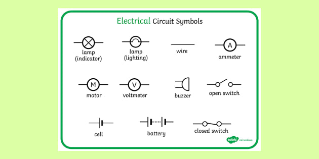
This physics video tutorial explains how to read a schematic diagram by knowing what each electric symbol represent in a typical electrical circuit. An electric circuit is a path in which electrons from a voltage or current source flow. Electrical diagram symbols represents devices and components of electrical and electronic circuits. Lamp / light bulb symbols. Apart from the circuit symbols, each device is also designated a short name.
Circuit Diagrams - GCSE Physics (Combined Science) AQA Revision - Study Rocket from studyrocket.co.uk Electrical symbols and electronic circuit symbols are used for drawing schematic diagram. Thus in circuit diagrams and schematics, graphical symbols identify and represent electrical and electronic devices and show how they are electrically connected together while a the connecting leads or pins of a component in a schematic diagram can be identified using letters or abreviations. It can be used for a zero potential reference point from where current is measured. As nowadays there is no single standard. For example, a simple circuit diagram of an electric torch would look like all of the symbols used in circuit diagrams represent a specific electronic component. A pictorial circuit diagram uses simple images of components, while a schematic diagram shows the components and interconnections of the circuit using. Learn vocabulary, terms and more with flashcards, games and other study tools. This enables anyone to read a circuit diagram and know what it.
An electric circuit can be represented by a circuit diagram, which uses standard symbols to represent the parts of the circuit.
Start studying electric circuit diagram symbols. As mentioned above, the circuit diagram visualizes electrical circuits. Draw the single lin e and wiring diagram of three lambs connectected in series and parallel? An electric circuit can be represented by a circuit diagram, which uses standard symbols to represent the parts of the circuit. Complete circuit symbols of electronic components. It is a continuous and closed path through which electric current flows. All electric circuits must have a voltage source, such as a battery, and a conductor, which is usually wire. From transistors to logic gates whether you're looking for transistors, relays, amplifiers, or power sources, lucidchart has the circuit symbols you need to make a precise circuit diagram. These diagrams are drawn using standard industrial symbols. Electrical circuits library contains 49 electrical element symbols of electrical and electronic devices, including ignitors, starters, transmitters, circuit protectors, transducers, radio and audio equipment. What is the circuit diagram symbol for a cell? A switch used to turn a circuit on (closed) and off (open). Two cells in series symbol.