Home
› Ladder Logic Diagram Examples - Plc Programming How To Read Ladder Logic / Ladder logic ladder diagrams ladder diagrams are specialized schematics commonly used to document industrial control logic systems.
Ladder Logic Diagram Examples - Plc Programming How To Read Ladder Logic / Ladder logic ladder diagrams ladder diagrams are specialized schematics commonly used to document industrial control logic systems.
Ladder Logic Diagram Examples - Plc Programming How To Read Ladder Logic / Ladder logic ladder diagrams ladder diagrams are specialized schematics commonly used to document industrial control logic systems.. † basic ladder logic symbols † ladder logic diagram † ladder logic evaluation † start/stop logic objectives upon completion of this chapter, you will be able to: How to draw ladder diagramsdid this video help you? Ladder diagrams (sometimes called ladder logic) are a type of electrical notation and symbology frequently used to illustrate how electromechanical switches and relays are interconnected. In the ladder diagram, the programming language that used to create the program to control the plc system is known as 'ladder diagram language. However, when you start with a blank page to design a new control system, large or small.
In the ladder diagram, the programming language that used to create the program to control the plc system is known as 'ladder diagram language. We, however, have an or logic situation with the test switch in that it is required to give an output of lamp on regardless of whether there is a signal from the and system. I will start with the very basic ladder. The above diagram depicts a ladder logic programming example, illustrating an input/output circuit. 1/0) is closed, the output coil pl1 (o:
What Is Ladder Logic Ladder Logic Diagram Examples from realpars.com The device mentioned above is known as a programmable logic controller or plc for short and the software that enables this virtual circuit building is known as ladder logic or ladder diagram. The function block diagram and the ladder diagram are thus of the form shown in figure 1.37. Typically, we'd want the motor to keep running after the button has been released. The input and output addresses are shown in the ladder logic. 3/0) is energized closing all (o: Key takeaways ladder diagrams (sometimes called ladder logic) are a type of electrical notation. 2basic ladder logic programming chapter topics: Ladder logic examples can be hard to find, though.
When the on button is pushed, a stacker starts stacking plywood sheet at position a.
No i/o addresses yet.) thought process Below is a simplified drawing of a control circuit and one of our ladder logic diagram examples. The function block diagram and the ladder diagram are thus of the form shown in figure 1.37. Motion process reciprocating a work piece must travel back and forth on a conveyor. A sensor is used to stop the conveyor at b. Programmable logic controllers or plcs are digital computers used to perform control functions, usually for. They are called ladder diagrams because they resemble a ladder, with two vertical rails (supply power) and as many rungs (horizontal lines) as there are control circuits to represent. I will start with the very basic ladder. How to draw ladder diagramsdid this video help you? Ladder logic diagram example 1 computer aided manufacturing tech 4/53350 27 task: The input and output addresses are shown in the ladder logic. Draw a ladder diagram that will cause the output, pilot light pl2, to be on when selector switch ss2 is closed, push button pb4 is closed and limit switch ls3 is open. Simple start/stop ladder logic relay this is how the ladder diagram looks for a simple start/stop function.
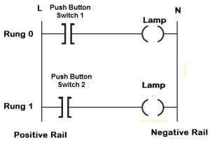
The above diagram depicts a ladder logic programming example, illustrating an input/output circuit. They are called ladder diagrams because they resemble a ladder, with two vertical rails (supply power) and as many rungs (horizontal lines) as there are control circuits to represent. Draw a ladder diagram that will cause the output, pilot light pl2, to be on when selector switch ss2 is closed, push button pb4 is closed and limit switch ls3 is open. The diagram shows the circuit for switching on or off an. Ladder diagrams (sometimes called ladder logic) are a type of electrical notation and symbology frequently used to illustrate how electromechanical switches and relays are interconnected.
Plc Programming Basics Devices And Ladder Logic from www.watelectronics.com The function can be used to start and stop anything like a motor. The example below shows a ladder diagram with pushbuttons (pb), control relays (cr), a motor (m) and a light (l). 5.1 ladder diagrams as an introduction to ladder diagrams, consider the simple wiring diagram for an electrical circuit in figure 5.1a. 3/0) is energized closing all (o: Develop ladder logic for an automatic paint process. No i/o addresses yet.) thought process This article will briefly describe what ladder logic is and go over some examples of how it functions. The two vertical lines are called rails and attach to opposite poles of a power supply, usually 120 volts ac.
No i/o addresses yet.) thought process
The appearance is what led to being called ladder logic, since it superficially resembles a ladder. But, these days the terms ladder diagram, ladder logic diagram, ladder drawing, ladder control, ladder circuit, control logic diagram and logic diagram (to name a few) are all used to describe relay logic circuits and ladder logic programming. Ladder logic examples can be hard to find, though. We, however, have an or logic situation with the test switch in that it is required to give an output of lamp on regardless of whether there is a signal from the and system. The function can be used to start and stop anything like a motor. Especially because the names of the ladder logic examples often are confusing and even misguiding. Programmable logic controllers or plcs are digital computers used to perform control functions, usually for. The plc ladder logic programming is really easy as compared to the arduino or any other microcontroller programming. Plc's together with ladder logic has transformed the industrial automation industry. Key takeaways ladder diagrams (sometimes called ladder logic) are a type of electrical notation. † basic ladder logic symbols † ladder logic diagram † ladder logic evaluation † start/stop logic objectives upon completion of this chapter, you will be able to: Ladder logic ladder diagrams ladder diagrams are specialized schematics commonly used to document industrial control logic systems. In the ladder diagram, the programming language that used to create the program to control the plc system is known as 'ladder diagram language.
A ladder logic example of a trafic light can, as an example, vary a lot. However, a major problem is the fact that the user must keep the button pressed for the motor to run. Check out my list of all the best examples of plc programs. Especially because the names of the ladder logic examples often are confusing and even misguiding. It is a graphical plc programming language which expresses logic operations with symbolic notation.
Https Hvacrknowlagecenter Homestead Com Ladder Pdf from The device mentioned above is known as a programmable logic controller or plc for short and the software that enables this virtual circuit building is known as ladder logic or ladder diagram. When the on button is pushed, a stacker starts stacking plywood sheet at position a. Simple ladder logic program examples ladder diagram examples and solutions to simple plc logic functions. However, when you start with a blank page to design a new control system, large or small. The above diagram depicts a ladder logic programming example, illustrating an input/output circuit. The diagram shows the circuit for switching on or off an. This symbology is sometimes used to demonstrate the interconnection of electromechanical switches and relays. 1/0) is closed, the output coil pl1 (o:
Ladder logic programming for industrial controllers has evolved significantly over the years, and now supports advanced functionality such as process control, motion control, data manipulation, networking, and data acquisition.
Ladder diagrams (sometimes called ladder logic) are a type of electrical notation and symbology frequently used to illustrate how electromechanical switches and relays are interconnected. Ladder diagram, better known as ladder logic, is a programming language used to program plcs (programmable logic controllers). I will start with the very basic ladder. 2basic ladder logic programming chapter topics: 3/0) contacts and the pilot light pl1 will be lit. Ladder logic diagram example 1 computer aided manufacturing tech 4/53350 27 task: Ladder logic examples can be hard to find, though. Stack height is controlled by plc counter function. Then follow the procedure in part b.1 to program and test the ladder logic. When the on button is pushed, a stacker starts stacking plywood sheet at position a. Ladder logic programming for industrial controllers has evolved significantly over the years, and now supports advanced functionality such as process control, motion control, data manipulation, networking, and data acquisition. No i/o addresses yet.) thought process The diagram shows the circuit for switching on or off an.
Ladder logic ladder diagrams ladder diagrams are specialized schematics commonly used to document industrial control logic systems logic diagram examples. Motion process reciprocating a work piece must travel back and forth on a conveyor.